

 简体中文
简体中文
 English
  عربى
عربى What Exactly is a Blower Motor?
A blower motor is closely associated with "wind" – it is a driving device that provides power for various fan equipment, and can be called the "power core" of the fan. If we liken the fan to an "air porter", the blower motor is its "muscle", capable of outputting energy to enable the fan to transport air or gas.
In essence, the blower motor belongs to a subcategory of electric motors and is a specialized device. Its core function is to efficiently convert electrical energy into mechanical energy: when an electric current passes through the windings, it generates electromagnetic force to drive the rotor to rotate. The rotor then drives the fan blades or impellers through the rotating shaft, forming a directional airflow.
Compared with ordinary motors, blower motors have many unique features. It needs to maintain stable torque output at different speeds. For example, when the air outlet is blocked, it can automatically increase torque to maintain air volume. It also needs to adapt to various air pressure environments, whether it is low-pressure ventilation or high-pressure air supply scenarios, it can operate stably.
In terms of application fields, blower motors can be found in various aspects of life and production. In the civil field, it is the "heart" of household appliances such as air conditioners and range hoods. In the industrial field, it is used for factory ventilation, cooling tower temperature reduction, boiler air supply, etc. In the medical field, oxygen generators and ventilators also rely on it to ensure patients' breathing needs.
Simply put, a blower motor is a power device customized to "promote air flow". Its performance determines the efficiency, stability and applicable range of the fan. Without it, even the most sophisticated fan is just a pile of static metal parts, unable to realize any air transportation function.
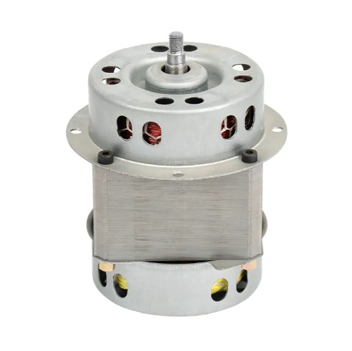
What Unique Structures Compose a Blower Motor?
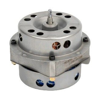
The reason why the blower motor can efficiently drive the fan to operate is inseparable from its carefully designed internal structure. It is an integral whole with multiple precision components working together, and each component has its irreplaceable function, jointly supporting the whole process of "converting electrical energy into air flow power". The following is a detailed analysis of its core structure:
| Structural Components |
Core Composition | Main Functions | Typical Application Scenarios |
| Stator | Laminated silicon steel core + enameled copper/aluminum windings | Generates a rotating magnetic field to provide power for the rotor; winding parameters determine voltage adaptability and torque characteristics | All types of blower motors, especially industrial high-load scenarios |
| tor | Squirrel-cage type (core + conductive bars + short-circuit rings)/Wound type (insulated windings + slip rings) + high-strength steel shaft | Cuts the stator's magnetic field to generate induced current, converting it into rotational mechanical energy; transmits power to fan blades through the shaft | Squirrel-cage: household/small and medium industrial fans; Wound: large industrial fans requiring frequent start-stop |
| Housing | Cast iron/aluminum alloy, some with heat sinks | Protects internal components from impurities; accelerates heat dissipation through heat sinks; fixes the motor position | Aluminum alloy (rust-proof) for humid environments; heat sink design for high-temperature environments |
| Bearings | Ball bearings (inner ring + outer ring + balls + cage)/Sliding bearings (wear-resistant bushings) | Reduces rotational friction of the shaft, ensuring stable rotor operation | Ball bearings: high-speed fans (e.g., industrial exhaust fans); Sliding bearings: low-noise scenarios (e.g., household air conditioners) |
| Commutation System (DC) | Brushed (graphite brushes + copper commutator)/Brushless (Hall sensor + electronic controller) | Changes rotor current direction to maintain continuous rotation; brushless systems reduce wear and noise | Brushed: low-cost devices (e.g., small fans); Brushless: precision equipment (e.g., medical ventilators) |
| Auxiliary Components | Capacitor, terminal box, thermal protector | Capacitor assists single-phase motor startup; terminal box protects circuit connections; thermal protector prevents overload/overheating damage | Capacitor: household single-phase fans; Thermal protector: all motors requiring continuous operation (e.g., workshop ventilators) |
These components cooperate with each other to form an organic whole: the stator generates a rotating magnetic field, the rotor rotates under the action of the magnetic field, the bearings reduce friction, the housing provides protection and heat dissipation, the commutation system (DC motor) ensures the stability of the rotation direction, and the auxiliary components ensure safety and convenience. If any component fails, it may lead to the degradation of motor performance or even complete failure.
What is the Core Technical Principle of a Blower Motor?
The blower motor seems complex, but its core operating principle always revolves around the basic physical law of "electromagnetic induction". Simply put, it generates a magnetic field through electrical energy, then uses the interaction between magnetic fields to generate mechanical rotation, and finally realizes the conversion of "electrical energy → magnetic energy → mechanical energy". The following is a detailed analysis of this process:
1. Generation of Magnetic Field: The Magic of Electricity Generating Magnetism
The first step for a motor to operate is to "generate a magnetic field with electricity". This process follows Ampere's law: when an electric current passes through a conductor (here refers to the stator winding), a magnetic field will be generated around the conductor. The direction of the magnetic field can be judged by the right-hand screw rule (hold the wire with the right hand, the thumb points to the current direction, and the direction of the four fingers bending is the direction of the magnetic field around).
In AC blower motors, alternating current (current direction and magnitude change periodically with time) is input, so the direction of the magnetic field generated by the stator windings will also rotate with the change of current direction, forming a "rotating magnetic field". The speed of the rotating magnetic field (called synchronous speed) is related to the power frequency and the number of pole pairs of the motor. The formula is: synchronous speed = 60 × power frequency ÷ number of pole pairs. For example, under the power frequency (50Hz) power supply, the synchronous speed of a motor with one pair of poles is 3000 rpm, and that with two pairs of poles is 1500 rpm.
In DC blower motors, direct current (current direction is fixed) is input, and the stator windings generate a "constant magnetic field". In order for the rotor to rotate, it is necessary to continuously change the current direction of the rotor windings through a commutation system (brushes and commutators of brushed motors, or electronic controllers of brushless motors), so that the rotor magnetic field and the stator magnetic field always maintain an interactive state.
2. Rotation of Rotor: Driving by Magnetic Field Force
With a magnetic field, the next step is to use the force between magnetic fields to drive the rotor to rotate. This process follows the left-hand rule: stretch out the left hand, make the thumb perpendicular to the other four fingers and in the same plane, let the magnetic induction lines enter from the palm, the four fingers point to the current direction, and the direction pointed by the thumb is the direction of the force on the energized conductor in the magnetic field.
In AC motors, the rotating magnetic field of the stator will cut the conductive bars of the rotor (squirrel-cage rotor). According to the law of electromagnetic induction, an induced current (current in a closed loop) will be generated in the conductive bars. These conductive bars with current are in the rotating magnetic field and will be subjected to electromagnetic force, and the direction of the force is determined by the left-hand rule. Because the rotating magnetic field is annular, the electromagnetic force on each part of the rotor will form a rotating torque (torque), pushing the rotor to rotate in the direction of the rotating magnetic field. However, the actual speed of the rotor (called asynchronous speed) will be slightly lower than the synchronous speed (there is a slip rate), because only when there is a speed difference can the magnetic field continuously cut the conductive bars to generate induced current.
In DC motors, the stator generates a constant magnetic field. The rotor windings are connected with direct current through brushes (brushed motors) or electronic controllers (brushless motors). At this time, the rotor windings become "energized conductors", which are subjected to electromagnetic force in the stator magnetic field to form a rotating torque. When the rotor rotates to a certain angle, the commutation system will change the current direction of the rotor windings, so that the direction of the electromagnetic force remains unchanged, thus maintaining the continuous rotation of the rotor.
3. Speed Regulation: The Key to On-Demand Control
Fans need different air volumes in different scenarios, which requires the motor to be able to adjust the speed. The core of speed regulation is to change the rotating torque or magnetic field speed of the motor, and the specific methods vary according to the type of motor:
AC motor speed regulation:
Frequency conversion speed regulation:
Adjust the synchronous speed of the stator rotating magnetic field by changing the power frequency, thereby changing the rotor speed. For example, reducing the 50Hz power frequency to 25Hz will halve the synchronous speed, and the rotor speed will also decrease accordingly. This method has a wide speed regulation range and high precision, and is the mainstream speed regulation method for modern industrial fans.
Voltage regulation speed regulation: Adjust the speed by changing the supply voltage of the stator windings. When the voltage decreases, the stator magnetic field weakens, the electromagnetic force on the rotor decreases, and the speed decreases. However, this method has a limited speed regulation range and low efficiency, and is mostly used in small fans (such as the gear adjustment of household fans).
Pole changing speed regulation: Adjust the number of pole pairs of the motor by changing the connection mode of the stator windings (such as changing from 2 pairs to 4 pairs), thereby reducing the synchronous speed. This method can only realize fixed gear speed regulation (such as high and low gears), and is suitable for scenarios that do not require continuous speed regulation.
DC motor speed regulation:
Voltage regulation speed regulation: The speed of a DC motor is proportional to the supply voltage (under a certain load). Therefore, the speed can be smoothly adjusted by adjusting the input voltage (such as using a thyristor or PWM controller). For example, reducing the voltage of a 12V DC motor to 6V will roughly halve the speed. This method is simple and efficient, and is widely used in DC fans (such as automobile cooling fans).
Magnetic regulation speed regulation: Adjust the speed by changing the strength of the stator magnetic field (applicable to excited DC motors). When the magnetic field weakens, the rotor needs a higher speed to generate enough back electromotive force to balance the power supply voltage, so the speed will increase. However, this method has a limited speed regulation range and may affect the motor life.
4. Torque Balance: Guarantee for Stable Operation
During the operation of the fan, the torque output by the motor needs to balance with the load torque of the fan (mainly the torque generated by air resistance) to maintain a stable speed. When the load torque increases (such as the fan filter is blocked), the speed of the motor will temporarily decrease. At this time, the stator magnetic field cuts the rotor faster, the induced current increases, and the electromagnetic torque also increases until it rebalances with the load torque and the speed returns to stability (AC motor); or the controller detects the increase in current and automatically increases the voltage to increase the torque (DC motor). Conversely, when the load torque decreases, the motor speed will temporarily increase, and the torque will decrease accordingly, eventually reaching a new balance.
This torque adaptive adjustment capability is an important feature that distinguishes blower motors from ordinary motors, and is also the key to their stable operation in complex air flow environments.
What Functions Does a Blower Motor Perform?
As the core power source of the fan, the function design of the blower motor directly serves the core goal of "promoting air flow efficiently, stably and flexibly". These functions not only determine the performance of the fan, but also affect its applicable scenarios and user experience. The following are the main functions and detailed analysis of the blower motor:
1. High Torque Output: "Power Guarantee" to Cope with Complex Loads
Torque is the moment generated when the motor rotates, which is commonly referred to as "rotational power". The primary function of the blower motor is to output sufficient torque to overcome loads such as air resistance and fan blade inertia, and promote the normal operation of the fan.
Starting torque: The motor needs to overcome the static resistance of the fan (such as the gravity of the fan blades and the static friction of the bearings) at the moment of starting, so it must have sufficient starting torque. For example, the fan blades of large industrial fans are heavy, and the motor needs to output several times the rated torque to "drive" the fan blades to rotate at startup; otherwise, it may have difficulty starting or "seize up".
Rated torque: The torque continuously output by the motor at the rated speed must match the load torque of the fan under normal working conditions. For example, the rated torque of the motor of a household range hood must be able to overcome the resistance of oil fume passing through the filter and pipeline to ensure stable exhaust air volume.
Overload torque: When the fan encounters a sudden increase in load (such as the filter being suddenly blocked by a large amount of oil), the motor must be able to output torque exceeding the rated value for a short time to avoid a sudden drop in speed or shutdown. The overload torque of high-quality blower motors can reach 1.5-2 times the rated torque, and can operate in the overload state for tens of seconds without damage.
This powerful torque output capability enables the blower motor to adapt to various load scenarios from slight ventilation to strong exhaust.
2. Wide Range Speed Regulation: "Flexibility" to Adjust Air Volume on Demand
The demand for air volume varies greatly in different scenarios (for example, air conditioners need large air volume for cooling in summer, while only small air volume for ventilation in spring and autumn). Therefore, the blower motor must have a speed regulation function to adjust the air volume by changing the speed (the air volume is roughly proportional to the speed).
Multi-gear speed regulation: Fixed speed gears (such as low, medium and high) are set through mechanical switches or electronic buttons, which is simple to operate and low in cost. It is common in household fans, desktop hair dryers and other equipment. For example, the "cold air gear" of a hair dryer corresponds to low speed, and the "hot air strong gear" corresponds to high speed.
Stepless speed regulation: It can continuously adjust the speed within a certain range to achieve smooth changes in air volume. For example, the blower motor of central air conditioning can adjust the speed in real time through a thermostat to keep the room temperature near the set value, avoiding sudden cold and heat; industrial fans can achieve 0-100% rated speed continuous adjustment through frequency converters to meet the ventilation needs of different production links.
Intelligent speed regulation: Combine sensors and control systems to realize automatic speed regulation. For example, the exhaust fan motor with smoke sensor can automatically increase the speed according to the smoke concentration; the cooling fan motor of the automobile engine will automatically adjust the speed according to the coolant temperature (stop when the temperature is low, and run at high speed when the temperature is high).
Speed regulation function not only improves the applicability of the fan, but also can significantly save energy – reducing the speed when the air volume demand is low can greatly reduce the power consumption of the motor (the motor power is roughly proportional to the cube of the speed; if the speed is halved, the power is about 1/8 of the original).
3. Efficient Energy Conversion: "Energy-Saving Core" to Reduce Energy Consumption
When the motor is working, part of the electrical energy will be converted into heat energy (such as winding resistance heating, iron core eddy current heating) and wasted. The energy conversion efficiency (the ratio of output mechanical energy to input electrical energy) is an important index to measure the motor performance. The high-efficiency and energy-saving functions of blower motors are mainly reflected in the following aspects:
Material optimization: High-conductivity copper wire windings (smaller resistance and less heat than aluminum wires) and low-loss silicon steel sheets (reducing eddy current loss) are used to reduce energy waste from the source. For example, the thickness of the iron core silicon steel sheet of high-efficiency motors can be as thin as 0.23 mm, and the surface is coated with an insulating layer to further suppress eddy currents.
Structural design: By optimizing the distribution of stator windings (such as using distributed windings instead of concentrated windings) and the slot design of the rotor, the magnetic field distribution is more uniform, and hysteresis loss is reduced. At the same time, high-precision bearing and rotating shaft processing technology reduce mechanical friction loss and improve overall efficiency.
Intelligent control: Combine frequency conversion technology to achieve "on-demand output" – when the fan load is light, the motor automatically reduces the speed and current to avoid "using a large horse to pull a small cart" energy waste. For example, the blower motor of household inverter air conditioners can reach an efficiency of more than 85%, which is 30% more energy-saving than traditional fixed-speed motors.
For fans that need to run for a long time (such as industrial ventilation systems and data center cooling fans), the energy-saving effect of high-efficiency motors is particularly significant, which can greatly reduce long-term operating costs.
4. Stable Operation: "Reliability Cornerstone" to Ensure Uniform Air Flow
The core function of the fan is to provide stable air flow, which depends on the stable operation capability of the motor – that is, to maintain the consistency of speed and torque under various working conditions, and avoid the air volume fluctuating due to fluctuations.
Speed stability: High-quality blower motors are equipped with high-precision bearings and dynamic balance correction technology to ensure that the radial runout of the rotor during rotation is controlled within 0.05 mm, thereby reducing speed fluctuations. For example, the speed fluctuation of the blower motor of medical ventilators must be controlled within ±1% to ensure the stability of the patient's breathing air flow.
Anti-interference ability: It can resist external interference such as power supply voltage fluctuation and ambient temperature change. For example, when the grid voltage fluctuates from 220V to 198V (±10%), the motor can maintain a speed deviation of no more than 5% through the built-in voltage stabilizing circuit or magnetic circuit design to ensure stable air volume.
Continuous operation capability: It has durability for long-term continuousoperation. Industrial-grade blower motors usually adopt Class H insulation materials (temperature resistance up to 180°C) and are equipped with efficient heat dissipation systems, enabling 24-hour uninterrupted operation to meet the continuous ventilation needs of factory workshops, subway tunnels and other scenarios.
5. Safety Protection: "Protective Barrier" to Prevent Failures
Blower motors may face risks such as overload, overheating, and short circuits when operating in complex environments, so it is crucial to have multiple built-in safety protection functions:
Overload protection: When the motor load exceeds the rated value (such as the fan blade being stuck by foreign objects), the current will increase sharply. The overload protector (such as a thermal relay, current sensor) will cut off the power supply within 1-3 seconds to prevent the windings from burning. After the fault is eliminated, manual reset (some models can automatically reset) is required to restart.
Overheat protection: The temperature is monitored in real time through a thermistor embedded in the winding. When the temperature exceeds the tolerance limit of the insulation material (such as Class B insulation motor exceeding 130°C), the power supply is immediately cut off. This protection is particularly important for motors with frequent start-stops or poor ventilation.
Short-circuit protection: When the winding insulation is damaged and causes a short circuit, the fuse or circuit breaker at the motor incoming line will blow quickly to cut off the power supply, avoiding fire or power failure.
Anti-reverse protection: Some motors (such as smoke exhaust fans) are equipped with direction detection devices. If the rotor reverses due to wrong wiring (which will reduce air volume or even damage the fan), the protection device will immediately stop and alarm to ensure the fan runs in the correct direction.
6. Low-Noise Operation: "Detail Advantage" to Improve User Experience
Noise mainly comes from mechanical vibration (bearing friction, rotor imbalance) and electromagnetic noise (vibration caused by magnetic field changes) during motor operation. Blower motors achieve low-noise function through optimized design to improve user experience:
Mechanical noise reduction: Precision ball bearings (with small friction coefficient) are used and filled with long-acting grease to reduce rotational friction noise; the rotor is corrected by dynamic balance to reduce vibration noise during rotation (vibration is controlled below 0.1mm/s).
Electromagnetic noise reduction: By optimizing the arrangement of stator windings and magnetic circuit design, electromagnetic force vibration caused by magnetic field harmonics is reduced; the housing is made of sound-insulating materials (such as damping coatings) to absorb vibration sound waves. For example, the blower motor of household air conditioner indoor units can control the operating noise below 30 decibels (equivalent to a whisper), which does not affect sleep.
These functions cooperate with each other, enabling the blower motor to provide strong power, flexibly adapt to different needs, and at the same time take into account energy saving, safety and low noise, becoming the "all-round power source" of various fan equipment.
What Problems Can Blower Motors Solve?
The existence of blower motors is essentially to overcome various obstacles in the process of air flow and meet human demand for "controllable air flow" in production and life. From families to factories, from daily life to precision industry, it solves many key air-related problems as follows:
1. Solving the Problem of "Stagnant Air" in Enclosed Spaces
In closed rooms (such as homes, offices, meeting rooms) with closed doors and windows, long-term lack of air circulation will lead to a decrease in oxygen content, an increase in carbon dioxide concentration, and accumulation of harmful gases such as formaldehyde, oil fume, and body odor, causing dizziness, chest tightness and other discomfort.
Blower motor-driven ventilation systems (such as fresh air systems, exhaust fans) can form directional air flow: introduce fresh outdoor air into the room, and discharge dirty air at the same time to achieve air circulation. For example, a household fresh air system equipped with an efficient blower motor can change air 1-2 times per hour, keeping the air quality of the closed room at a healthy level, especially suitable for scenarios with frequent smog or need for deodorization after decoration.
In completely enclosed spaces such as underground garages and elevator shafts, blower motors are even more indispensable – they can timely discharge automobile exhaust and moldy odors, preventing harmful gas accumulation from causing safety hazards.
2. Solving the Problems of "Temperature Imbalance" and "Overheating"
Whether in life or production, temperature control is inseparable from the assistance of air flow, and the blower motor is the core power to realize temperature regulation:
Home temperature control: The indoor blower motor of the air conditioner drives the wind blades to send cold and hot air generated by the condenser into the room, making the room temperature quickly reach the set value through air circulation; the blower motor of the heating system accelerates the heat dissipation of the hot water radiator, making the room temperature rise more evenly (avoiding overheating near the radiator and cold corners).
Equipment heat dissipation: Computer hosts, projectors, industrial machine tools and other equipment generate a lot of heat during operation. If not dissipated in time, it will lead to performance degradation or even burnout. The cooling fan driven by the blower motor can force the heat out. For example, the cooling fan of the computer CPU relies on the motor to rotate at high speed (usually 3000-5000 rpm) to form air flow, controlling the chip temperature below 80°C.
Industrial temperature control: In high-temperature environments such as steel mills and glass factories, large axial flow fans driven by blower motors can discharge hot air in the workshop and introduce external cold air at the same time, reducing the working environment temperature and protecting workers' safety and stable operation of equipment.
3. Solving the Problem of "Pollutant Accumulation"
Various pollutants (dust, oil fume, chemical gases, etc.) will be generated in production and life. If not removed in time, they will endanger health or affect production quality. Blower motors solve this problem by driving different types of fans:
Kitchen oil fume: The blower motor of the range hood generates strong negative pressure (suction) to discharge oil fume generated during cooking through the pipeline to the outside, avoiding oil fume adhering to walls and furniture, and reducing human inhalation of harmful substances in oil fume (such as benzopyrene).
Industrial dust: In cement factories, flour mills and other places, dust collectors driven by blower motors collect dust particles in the air through filters or cyclone separators, reducing dust concentration, protecting workers' respiratory systems, and avoiding the risk of dust explosions.
Chemical waste gas: In laboratories and chemical plants, anti-corrosion fans (made of acid and alkali resistant materials) driven by blower motors pump toxic gases (such as formaldehyde, chlorine) generated in experiments into waste gas treatment devices to prevent leakage and environmental pollution.
4. Meeting the Demand for "Precise Air Flow" in Special Scenarios
In some scenarios with strict requirements on air flow speed and pressure (such as medical treatment, scientific research, precision manufacturing), odinary natural air flow cannot meet the demand, and precise control of blower motors is necessary:
Medical respiratory support: The blower motor of the ventilator can precisely control the air flow speed and pressure, deliver oxygen or air according to the patient's breathing rhythm, and help patients with difficulty breathing maintain normal breathing. Its speed control accuracy can reach ±1 rpm to ensure stable air flow.
3D printing forming: In FDM (Fused Deposition Modeling) 3D printing, the cooling fan driven by the blower motor needs to accurately blow to the newly extruded plastic wire to make it quickly solidify and shape to avoid deformation. The fan speed needs to be adjusted in real time according to the printing material (such as PLA, ABS) and layer height, which depends on the stepless speed regulation function of the motor.
Wind tunnel experiment: In wind tunnel equipment in the aerospace field, giant blower motors can drive fan blades to generate high-speed and stable air flow (wind speed can reach several times the speed of sound), simulating the flight environment of aircraft at high altitudes and testing their aerodynamic performance. The power of such motors can reach several thousand kilowatts, and they need to maintain stable operation under extreme pressure.
5. Solving the Problems of "Energy Waste" and "Equipment Loss"
Traditional fans often waste energy due to low motor efficiency and backward speed regulation methods, or are frequently damaged due to lack of protection functions. Blower motors solve these problems in the following ways:
Energy saving and consumption reduction: High-efficiency motors (such as IE3 and IE4 energy efficiency standards) are 10%-15% more efficient than traditional motors. Taking a 15kW industrial fan running 8 hours a day as an example, it can save about 12,000 yuan in electricity bills per year (calculated at 0.5 yuan/kWh).
Prolonging equipment life: The overload and overheating protection functions of the motor can prevent the fan from being damaged due to abnormal loads; the low-noise design reduces the wear of the fan structure caused by vibration and reduces the maintenance frequency. For example, industrial fans equipped with brushless motors have an average trouble-free operation time of more than 50,000 hours, which is 3-5 times that of traditional brushed motors.
From the comfort of daily life to the safety and efficiency of industrial production, blower motors have become an indispensable "invisible cornerstone" of modern society by solving various problems related to air flow.
How to Use Fans Driven by Blower Motors in Different Scenarios?
The use of blower motors needs to be flexibly adjusted according to specific scenarios to give full play to their best performance and extend their service life. The load requirements and environmental conditions vary greatly in different scenarios, and the operation focus is also different. The specific guidelines are as follows:
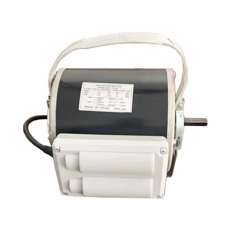
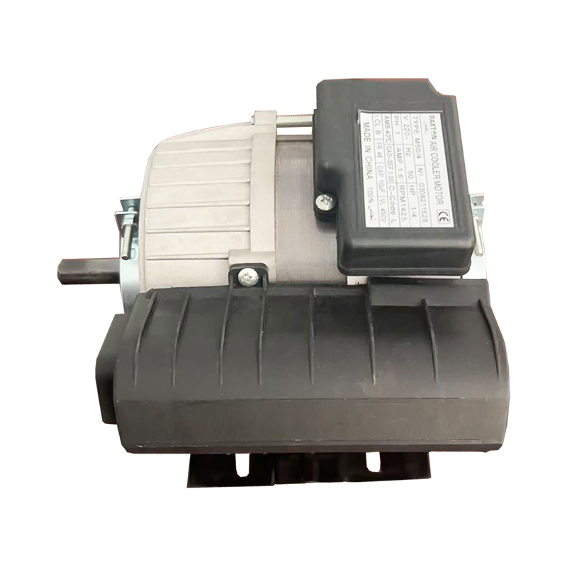
I. Household Scenarios (Air Conditioners, Range Hoods, Fans)
Household blower motors have small power (usually 50-500W), and the operation is centered on "convenience and energy saving", requiring attention to detailed maintenance:
1. Air Conditioner Blower Motor
Wind speed adjustment strategy: In high temperature in summer, first turn on the high-speed gear to cool down quickly (usually 3000-4000 rpm). When the room temperature is close to the set value (such as 26°C), switch to the medium and low-speed gear (1500-2000 rpm) to maintain a constant temperature, which can avoid frequent start-stops and reduce energy consumption; in winter heating, give priority to the low-speed gear to let the hot air rise and spread naturally, avoiding direct blowing on the human body and causing dry skin.
Filter cleaning and maintenance: A blocked filter will increase the air intake resistance by more than 30%, leading to a sharp increase in motor load. It is recommended to rinse the filter with clean water every 2-3 weeks (add neutral detergent when there is heavy oil pollution), and install it after drying. Especially in environments with dense oil fume or dust such as kitchens and streets, the cleaning cycle needs to be shortened to 1 week.
Start-stop protection skills: When leaving the room for a short time (within 1 hour), it is more cost-effective to keep running at low speed – the current at the moment of motor start is 5-7 times the rated value. Frequent start-stops not only consume electricity, but also accelerate winding aging.
2. Range Hood Blower Motor
Grasping the start-up timing: Turn on the machine 1-2 minutes before cooking to allow the motor to form negative pressure in advance (wind pressure is about 200-300Pa), which can effectively prevent oil fume from spreading to other areas of the kitchen and reduce the burden of post-cleaning.
Matching rotation speed to cooking scenarios: Use high-speed gear (2500-3000 rpm) for stir-frying and deep-frying to quickly discharge a large amount of oil fume through strong suction; switch to low-speed gear (1000-1500 rpm) for slow stewing and soup making to maintain basic oil fume discharge while reducing noise and energy consumption.
Regular cleaning of impellers: Oil fume adhesion will increase the weight of the impeller by 10%-20%, leading to a decrease in motor speed and increased vibration. The impeller needs to be disassembled and cleaned every 3 months: soak in warm water with baking soda for 10 minutes, soften the oil stains, and clean with a soft brush. Avoid scratching the impeller surface with steel wool.
3. Floor Fan/Table Fan Motor
Guaranteeing placement stability: The fan must be placed on a horizontal table with a gap of no more than 0.5mm between the bottom and the table. Otherwise, uneven force on the rotor will accelerate bearing wear and increase noise by 10-15 decibels.
Protection for continuous operation: Continuous operation at high speed (≥2500 rpm) should not exceed 4 hours. In high temperature in summer, the motor needs to be stopped for 15 minutes to cool down – when the motor temperature exceeds 70°C, the aging speed of the insulation layer will be accelerated by more than 2 times.
II. Industrial Scenarios (Workshop Ventilation, Dust Removal Systems, Cooling Towers)
Industrial blower motors have large power (1-100kW) and complex operating environments. Strict compliance with specifications is required to ensure safety and efficiency:
1. Workshop Ventilation Fan
Dynamic speed adjustment: Adjust in real time according to the number of people in the workshop – turn on high-speed gear during peak working hours (personnel density > 1 person/㎡) to ensure fresh air volume ≥30m³/person·hour; switch to low-speed gear or stop during lunch break or when no one is around, which can maintain air circulation and reduce energy consumption by more than 40%.
Belt drive maintenance: For belt drive, check the belt tightness every month: press the middle of the belt with fingers, and the sinking amount should be 10-15mm. Too loose will cause speed loss (up to 5%-10%), and too tight will increase the bearing load by 20% and aggravate wear.
Temperature monitoring and early warning: Regularly detect the motor housing temperature with an infrared thermometer, which should normally be ≤70°C (at an ambient temperature of 25°C). If the temperature rises sharply (exceeding 80°C), stop immediately for inspection: it may be lack of bearing oil (supplement lithium-based grease) or winding short circuit (detect insulation resistance with a megohmmeter, which should be ≥0.5MΩ).
2. Dust Removal Fan
Pretreatment before start-up: Check the cleanliness of the filter bag before start-up. If the resistance exceeds 1500Pa (detected by a differential pressure gauge), start the backblowing system to clean dust first – a blocked filter bag will double the fan outlet pressure, causing the motor current to exceed the limit (more than 1.2 times the rated value) and triggering overload protection shutdown.
Speed regulation mode selection: Avoid frequent speed changes (such as ≥3 times per minute). It is recommended to adopt the mode of "high-speed operation (80%-100% rated speed) + regular dust cleaning (once every 30 minutes)" to reduce the impact of current fluctuations on the motor windings.
Anti-corrosion sealing inspection: When handling corrosive gases (such as acid-base mist), disassemble the junction box every month to check whether the sealing rubber ring is aging (replace immediately if cracks appear), and apply Vaseline on the terminals to prevent poor contact due to corrosion.
3. Cooling Tower Fan
Water temperature linked speed regulation: Link with a frequency converter through a temperature sensor (accuracy ±0.5°C). When the outlet water temperature >32°C, increase the speed by 5% for every 1°C increase; when <28°C, reduce the speed to achieve "on-demand heat dissipation", which is more than 30% energy-saving than the fixed speed mode.
Winter anti-freezing operation: When the temperature is ≤0°C, if the fan needs to run, reduce the speed to 30%-50% of the rated value (reduce air volume and heat loss), and turn on electric heating (power ≥5kW) at the same time to ensure the water temperature in the tower ≥5°C, avoiding impeller and shell jamming due to freezing.
III. Automotive Scenarios (Cooling Fans, Air Conditioner Blowers)
Automotive blower motors work in vibrating and high-temperature environments (engine compartment temperature can reach 80-120°C), and attention should be paid to protection during use:
1. Engine Cooling Fan
Cleaning after cooling: After turning off the engine, wait for more than 30 minutes until the motor temperature drops below 60°C before flushing – cold water on a hot motor will cause uneven thermal expansion and contraction between the housing and internal components, possibly causing cracks (especially aluminum alloy housings).
Abnormal noise early warning and handling: If a "squeaking" sound (bearing lack of oil) occurs during rotation, timely add high-temperature grease (temperature resistance ≥150°C); if a "clicking" sound (impeller rubbing) occurs, check whether the fixing bolts are loose (torque should meet the manual requirements, usually 8-10N·m) to prevent impeller deformation and aggravated wear.
2. Air Conditioner Blower
Filter replacement cycle: Replace the air conditioner filter every 10,000-20,000 kilometers (shorten to 10,000 kilometers in harsh road conditions). A blocked filter will increase the air intake resistance by 50%, leading to a 20%-30% increase in motor current, which may burn the windings after long-term operation.
Gear operation specifications: When switching gears, adjust step by step (from "off"→"low speed"→"medium speed"→"high speed") with an interval of 1-2 seconds each time to avoid instantaneous high current impact (up to 6 times the rated value) damaging the speed control resistor.
IV. Medical Scenarios (Ventilators, Oxygen Generators)
Blower motors in medical equipment have extremely high requirements for precision (speed error ≤±1%) and stability, and operation must strictly follow regulations, with "precision and safety" as the core:
1. Ventilator Blower Motor
Parameter calibration process: Calibrate with professional software before use to ensure the speed matches the tidal volume and respiratory frequency (for example, the adult tidal volume of 500ml corresponds to a speed of 1500 rpm, with an error ≤5 rpm). After calibration, verify with a standard air pump to ensure the air flow fluctuation ≤3%.
Disinfection protection points: When disinfecting, only disinfect the air circuit pipes, masks and other patient-contact parts (wipe with 75% alcohol or high-temperature sterilization). It is strictly forbidden to let disinfectant enter the motor interior – liquid infiltration will cause the winding insulation resistance to drop (<0.5MΩ), leading to short-circuit faults.
Power redundancy guarantee: Must be connected to a UPS uninterruptible power supply (battery life ≥30 minutes), and test the power-off switching function regularly (monthly) to ensure that the motor does not pause when the mains power is interrupted (speed fluctuation ≤2%), avoiding endangering the patient's breathing.
2. Oxygen Generator Blower Motor
Intake environment control: The air inlet should be away from kitchens (oil fume) and cosmetics (volatile substances). It is recommended to install a HEPA pre-filter (filtration accuracy ≥0.3μm) to prevent impurities from entering the motor and wearing the bearings (service life can be extended by more than 2 times) or blocking the molecular sieve (affecting oxygen concentration).
Load control strategy: Continuous operation for no more than 12 hours a day, stop for 30 minutes every 6 hours to allow the motor (temperature ≤60°C) and molecular sieve to cool naturally – high temperature will cause the adsorption efficiency of the molecular sieve to drop by 10%-15% and accelerate the aging of the motor insulation.
Summary: Core Principles Across Scenarios
Regardless of the scenario, the use of blower motors must follow three principles:
1.Load matching: Adjust the speed according to actual needs (air volume, pressure) to avoid "overcapacity" or overload operation;
2.Regular maintenance: Focus on key links such as cleaning, lubrication, and sealing to detect hidden dangers in advance;
3.Abnormal early warning: Judge abnormalities through sound (abnormal noise), temperature (overheating), and parameters (current/speed fluctuation), and stop in time for handling.
Following these principles can ensure long-term stable operation of the motor and maximize its performance value.
What Are the Tips for Using Fans Driven by Blower Motors?
Mastering the use skills of blower motors can not only improve the operation efficiency of the fan, but also extend the motor life and reduce energy consumption. These skills cover all links from start-up to maintenance, and are applicable to fan equipment in different scenarios:
1. Start-up Phase: Reduce Impact and Achieve Smooth Start
The current at the moment of motor start-up is 5-7 times the rated current (called "start-up inrush current"). Frequent or improper start-up will accelerate winding aging and bearing wear, so it is necessary to master correct start-up skills:
No-load/light-load start-up: Ensure the fan is no-load or light-load before start-up. For example, open the bypass valve before starting the dust removal fan to reduce pipeline pressure; check whether the impeller is stuck by foreign objects before starting the industrial fan (manually rotate the impeller to confirm flexibility).
Step-by-step start-up: For high-power motors (above 5kW), it is recommended to use star-delta start or soft starter to reduce the start-up current to 2-3 times the rated current, reducing the impact on the power grid and motor. When starting small household motors (such as fans), you can first turn on the low-speed gear, and then switch to the high-speed gear after 3-5 seconds.
Avoid frequent start-stop: When you need to pause for a short time (within 10 minutes), you can keep the motor running at low speed instead of stopping completely. For example, during the gap between cooking in the kitchen, the range hood can be turned to low speed instead of turning off to reduce the number of starts.
2. Operation Phase: Adjust on Demand for Energy Efficiency
The energy consumption of the fan during operation is closely related to the speed (power ≈ speed³). Reasonable adjustment of speed and load can greatly reduce energy consumption:
Adjust speed to match load: Dynamically adjust the speed according to actual needs to avoid "using a large horse to pull a small cart". For example:
When there is no one in the workshop, reduce the speed of the ventilation fan to 30%-50% of the rated value;
When the air conditioner is cooling, reduce the fan speed by 20%-30% after the room temperature reaches the set value;
When cleaning a small amount of dust with a vacuum cleaner, use the low-speed gear (motor speed below 10,000 rpm) to avoid unnecessary energy consumption.
Balance inlet and outlet pressure: The resistance at the inlet and outlet of the fan will directly affect the motor load. For example, minimize elbows when installing pipelines (each 90° elbow will increase resistance by 10%-15%); regularly clean the filter screen and impeller to keep the air flow smooth, so that the motor operates under low load.
Use natural wind assistance: When outdoor fans (such as cooling towers, roof ventilators) are running, adjust the fan angle according to the wind direction to use natural wind to reduce the motor load. For example, when the natural wind is in the same direction as the fan outlet, the speed can be appropriately reduced to ensure air volume while saving electricity.
3. Maintenance Phase: Detailed Maintenance to Extend Life
The life of the blower motor largely depends on daily maintenance. The following tips can effectively reduce faults:
Regular cleaning to prevent pollution and damage:
Motor housing and heat dissipation holes: Clean dust with compressed air or a soft brush every 1-2 weeks to avoid poor heat dissipation (especially in dusty environments such as textile mills and flour mills).
Windings and commutator (brushed motors): Open the housing for inspection every year, wipe the carbon powder on the commutator surface with alcohol to prevent poor contact; if there is oil on the winding surface, clean it with a dry cloth dipped in a small amount of gasoline (operate after power failure).
Bearing lubrication: Add lubricating oil (such as No. 3 lithium grease) to sliding bearings every 3-6 months, and supplement grease to ball bearings every year. The oil quantity should fill 1/2-2/3 of the bearing cavity; too much will cause poor heat dissipation.
Monitor status to detect faults early:
Listen to the sound: The motor should make a uniform "buzzing" sound during normal operation. If there is a "squeal" (bearing lack of oil), "friction sound" (rotor sweeping) or "abnormal noise" (loose parts), stop immediately for inspection.
Measure temperature: Touch the motor housing with your hand. The normal temperature should not be hot (≤70°C). If it exceeds this temperature or is partially overheated (such as one end of the bearing is significantly hotter than the other), it may be bearing wear or winding short circuit.
Check current: Measure the operating current with a clamp ammeter. If it exceeds 10% of the rated current, it indicates that the load is too large (such as a blocked filter) or there is a fault inside the motor (such as a winding short circuit), and the cause needs to be investigated.
Adapt to the environment to reduce loss:
Humid environment (such as bathroom, basement): Choose a motor with a waterproof housing (protection grade IP54 or above), and check the sealing rubber ring of the junction box every month for aging to prevent water ingress and short circuit.
High-temperature environment (such as boiler room, near oven): Choose a high-temperature resistant motor (Class H insulation), and install a cooling fan around the motor to ensure that the ambient temperature does not exceed the rated temperature of the motor (such as Class H motor does not exceed 180°C).
Corrosive environment (such as chemical plant, seaside): Choose a motor with a stainless steel housing and anti-corrosion windings, and spray anti-rust paint once a quarter to avoid component corrosion.
4. Safe Use: Avoid Risks and Prevent Accidents
Blower motor operation involves electricity and mechanical rotation, and the following safety tips should be noted:
Electrical safety:
Ground protection: The motor housing must be reliably grounded (ground resistance ≤4Ω) to prevent electric shock accidents caused by live housing when the winding insulation is damaged.
Avoid overload electricity use: The motor power supply line must match its power (such as 1.5kW motor needs ≥1.5mm² copper wire), and install a suitable circuit breaker (rated current is 1.2-1.5 times the motor rated current).
Thunderstorm protection: Outdoor motors need to install lightning protection devices to avoid lightning damage to the control circuit and windings.
Mechanical safety:
Protective cover is essential: The exposed parts of the fan impeller and motor shaft must be installed with a protective cover (grid spacing ≤12mm) to prevent personnel contact injury or foreign objects from being involved.
Prohibit illegal operations: Do not disassemble the housing or touch rotating parts during operation; during maintenance, the power must be disconnected and a "No switching on" sign must be hung to prevent mis-starting.
These skills seem subtle, but they can significantly improve the operation efficiency of the blower motor, extend its life, and reduce safety risks. Whether in household or industrial scenarios, they should be flexibly used according to actual needs to keep the motor in the best working condition.
How to Perform Daily Maintenance on Blower Motors?
Daily maintenance of blower motors is crucial to ensure their long-term stable operation. A systematic maintenance plan needs to be formulated from multiple dimensions such as cleaning, inspection, lubrication, and storage. The maintenance focus of different types of motors (such as AC/DC, brushed/brushless) is slightly different, but the core principle is consistent: prevention first, timely handling of small problems to avoid the expansion of faults.
1. Daily Cleaning: Keep the Motor "Clean"
The core goal of cleaning is to remove impurities such as dust and oil to prevent them from affecting heat dissipation, insulation, and mechanical operation:
Housing and heat dissipation system:
Frequency: Once a week in general environments, once a day in dusty environments (such as cement plants, woodworking workshops).
Method: Wipe the housing with a dry soft cloth; blow the heat dissipation holes and heat sinks with compressed air (pressure 0.2-0.3MPa) or clean with a soft brush to ensure no dust blockage. If there is oil, wipe with a cloth dipped in neutral detergent, then dry with a dry cloth.
Note: Do not flush the motor directly with water (except waterproof motors) to avoid water entering the interior and causing short circuits.
Internal components (regular disassembly and cleaning):
Frequency: 1-2 times a year, or adjusted according to the operating environment (once every 6 months in humid environments).
Method:
Disconnect the power supply and remove the motor housing (record the wiring method to avoid wrong connection during reinstallation).
Stator windings: Clean surface dust with a dry cloth or compressed air; if there is oil, gently wipe with a cloth dipped in alcohol (avoid pulling the windings hard).
Rotor and commutator (brushed motors): Gently polish the oxide layer and carbon powder on the commutator surface with fine sandpaper (above 400 mesh), then wipe clean with alcohol cotton; blow the dust on the rotor core with compressed air.
Sensors of brushless motors: Wipe the surface of the Hall sensor with a dry cloth to avoid dust affecting signal detection.
Note: After cleaning, check whether the winding insulation layer is intact; if damaged, repair immediately (paint with insulating paint).
2. Regular Inspection: Detect Potential Hazards in Time
The focus of inspection is the electrical performance, mechanical components, and connection status of the motor to achieve "early detection and early handling":
Electrical system inspection:
Wiring and insulation: Check whether the terminals in the junction box are loose every week (confirm by gently screwing with a screwdriver), and whether the wire insulation layer is aging and cracked; measure the winding-to-ground insulation resistance with a megohmmeter (should be ≥0.5MΩ, high-voltage motors ≥1MΩ). If it is lower than the standard, dry or replace the windings.
Capacitors (AC motors): Check the appearance of capacitors every 3 months. If there is bulging, leakage or shell deformation, replace with the same type of capacitor (capacity error does not exceed ±5%) to avoid affecting motor start-up and operation performance.
Controller (brushless motors): Check whether the controller indicator lights are normal (such as power light, fault light) every month, and measure whether the input and output voltages are within the rated range with a multimeter. If there is an abnormality, check the line or replace the controller.
Mechanical component inspection:
Bearings: Listen to the bearing operation sound every month (you can hold one end of a screwdriver against the bearing seat and put the other end to your ear). There should be no abnormal noise; measure the bearing temperature every 6 months (not exceeding ambient temperature +40°C). If the temperature is too high or there is abnormal noise, replace the bearing (choose the same type and precision grade, such as 6205ZZ).
Rotor and rotating shaft: Check whether the rotating shaft is bent every six months (measure radial runout with a dial indicator, should be ≤0.05mm), and whether the rotor is balanced (no obvious vibration during operation). If there is an abnormality, straighten the rotating shaft or re-do dynamic balance.
Fan blade and impeller connection: Check whether the connection between the fan blade (or impeller) and the motor shaft is loose (such as whether the bolts are tightened) every week to prevent danger caused by falling during operation.
Protection device inspection:
Overload protectors and thermal relays: Manually test once a month (press the test button, which should trip normally) to ensure sensitive action; check whether the set value matches the motor rated current (usually 1.1-1.25 times the rated current).
Lightning protection and grounding devices: Check the grounding resistance (≤4Ω) before the rainy season, and whether the lightning arrester indicator is normal to ensure effective protection of the motor in thunderstorms.
3. Lubrication Maintenance: Reduce Friction and Extend Component Life
Bearings are the most easily worn components in the motor. Good lubrication can significantly reduce the friction coefficient, reduce heat generation and loss:
Lubrication cycle:
Sliding bearings: Add oil every 3 months when the ambient temperature ≤35°C; add oil every 1-2 months when the temperature >35°C or in humid environments.
Ball bearings: Add grease every 6-12 months in ordinary environments; add grease every 3-6 months in high-speed (>3000 rpm) or high-temperature environments.
Lubricant selection:
Sliding bearings: Choose No. 30 or No. 40 mechanical oil (moderate viscosity, no solidification at low temperature, no loss at high temperature).
Ball bearings: Choose lithium-based grease (such as No. 2 or No. 3), which is high-temperature resistant (-20°C to 120°C) and has good water resistance, suitable for most scenarios; choose composite calcium sulfonate grease for high-temperature environments (>120°C).
Lubrication method:
Sliding bearings: Unscrew the oil cup cover, add lubricating oil to the oil level line (about 1/2 of the bearing cavity), avoid excessive oil causing leakage or poor heat dissipation.
Ball bearings: Open the bearing cover, fill the bearing cavity with grease with a special tool (fill 1/2-2/3), rotate the bearing to distribute the grease evenly, then cover the bearing cover (pay attention to sealing to prevent dust from entering).
4. Storage Maintenance: "Fresh-keeping" Skills for Long-term Shutdown
If the motor needs to be out of service for a long time (more than 1 month), special maintenance measures must be taken to prevent component aging or damage:
Cleaning and drying: Thoroughly clean the inside and outside of the motor before storage, blow dry possible moisture with a heat gun (temperature ≤60°C), and ensure the windings and bearings are completely dry.
Anti-rust treatment: Apply anti-rust oil (such as Vaseline) to the exposed part of the rotating shaft, wrap it with plastic film; spray a thin layer of anti-rust paint on the metal housing (especially in humid environments).
Insulation protection: Run with electricity for 30 minutes every 2-3 months (no-load or light-load) to use the motor's own heat to drive away moisture and prevent the winding insulation from aging due to moisture; brushless motors need to power on the controller at the same time to avoid capacitor failure.
Storage environment: Choose a dry, ventilated warehouse without corrosive gases. The motor should be placed horizontally on skids (avoid direct contact with the ground to prevent moisture), away from heat sources and vibration sources; if it is a vertical motor, fix the rotating shaft to prevent bending.
5. Fault Pretreatment: Solve Small Problems on the Spot
In daily maintenance, if minor faults are found, they can be handled on the spot to avoid expansion:
Slight abnormal noise of bearings: Add grease in time; if the abnormal noise persists, check for foreign objects, remove them and observe the operation status.
Loose wiring: Tighten the terminals with a screwdriver, and apply antioxidant (such as Vaseline) at the wiring to prevent oxidation and rust.
Slight moisture of windings: Run the motor at no-load for 1-2 hours to drive away moisture with its own heat, or irradiate the windings with an infrared lamp (distance >50cm) todry them.
The core of daily maintenance is "meticulousness" and "regularity" – even seemingly insignificant dust or a loose screw may cause major faults in long-term operation. By formulating and implementing a complete maintenance plan, the service life of the blower motor can be extended by more than 30%, while maintaining efficient and stable operation.
Common Faults of Blower Motors and Cause Analysis
Blower motors are inevitably prone to faults during long-term operation. Understanding the manifestations and causes of common faults can help quickly locate problems and reduce downtime. The following is a detailed analysis of various faults:
| Fault Phenomenon | Possible Cause Categories | Specific Causes | Typical Manifestations |
| Failure to start | Electrical faults | Poor power contact, blown fuse, low voltage; winding short circuit/open circuit/grounding; brushless motor controller damage | No response after power-on, or only a faint "buzzing" sound |
| Mechanical faults | Severe bearing wear (ball fragmentation, bushing seizure), foreign objects between rotor and stator; fan blades entangled or impeller rubbing against housing | Difficulty in manually rotating the rotor, may trip during startup | |
| Protection device action | Protector not reset after overload/overheating | Power supply is normal, but the motor has no response | |
| Abnormal noise | Mechanical noise | Bearing lack of oil/wear, rotor imbalance (uneven blade wear, shaft bending); loose housing or fan blade fixing screws | "Squeaking" (lack of oil), "gurgling" (bearing wear), or "tapping" (component collision) sounds |
| Electromagnetic noise | Winding short circuit/wrong wiring (such as three-phase open phase); uneven air gap between stator and rotor | "Hissing" sound or high-frequency electromagnetic hum that changes with speed | |
| Motor overheating | Overload | Increased fan resistance (blocked filter, excessive pipe elbows, blocked air outlet); long-term operation beyond rated power | Housing temperature exceeds 70°C (at 25°C ambient temperature), may trigger thermal protection shutdown |
| Poor heat dissipation | Faulty cooling fan (brushless motors), blocked heat dissipation holes; ambient temperature exceeding 40°C | Abnormal increase in winding temperature, insulation layer may emit a burnt smell | |
| Electrical/mechanical faults | Winding short circuit, three-phase current imbalance; increased bearing friction due to wear | Local temperature rise (e.g., bearing area significantly overheats) | |
| Abnormal speed | Low speed | Insufficient power supply voltage (<90% of rated value); winding faults (turn-to-turn short circuit/rotor open circuit); overload | Obvious reduction in air volume, motor runs with difficulty |
| High speed | High power frequency (AC motors); controller failure (DC/brushless motors); fully open air outlet (no-load) | Abnormal increase in air volume, may be accompanied by increased noise |
Excessive vibration: Vibration exceeding the allowable range (usually ≤0.1mm/s) during motor operation will cause loose screws, accelerated component wear, and even overall resonance. Causes include:
Rotor imbalance: The center of gravity of the rotor does not coincide with the center of rotation (such as blade wear, shaft bending), generating centrifugal force during rotation, leading to vibration.
Installation issues: Motor installed unevenly (horizontal deviation exceeding 0.5mm/m), loose anchor screws, or misalignment between fan and motor shafts (concentricity deviation exceeding 0.1mm).
Bearing damage: Bearing ball fragmentation or cage damage causes irregular vibration during rotor rotation.
Electromagnetic imbalance: Three-phase current imbalance or winding asymmetry generates periodic electromagnetic force pulsation, causing vibration.
Excessive sparking in brushed motors: Brushed motors generate a small amount of sparks at the contact between brushes and commutators during operation, but excessive sparks (exceeding 1/4 of the commutator area) are abnormal. Causes include:
Severe brush wear or mismatched models: Insufficient brush length (shorter than 5mm), small contact area with commutator, or mismatched brush hardness and resistivity leading to poor contact.
Commutator damage: Uneven wear (grooves) on the commutator surface, protruding insulation between copper sheets, or commutator eccentricity causing unstable contact between brushes and commutator.
Winding faults: Rotor winding short circuit or open circuit causes sudden current changes during commutation, increasing sparks.
Improper brush pressure: Excessive pressure (increasing friction) or insufficient pressure (poor contact) of the brush spring can cause excessive sparking.
Accurately judging the cause of faults requires combining "observation, listening, and measurement": observe whether the appearance is damaged, listen to abnormal operation sounds, and measure voltage, current, and temperature with instruments. Most faults can be prevented from completely damaging the motor if handled in time; if self-inspection is difficult, contact professional maintenance personnel and do not force operation.


 Home
Home  Tel.: +86-13819807486
 Whatsapp:+86 13819807486
 E-mail:


